Un altra Ipotesi d'utilizzo per i TUU

Progetti, domande e idee sparse sull'autocostruzione delle elettroniche
Avatar utente
Luc1gnol0
sostenitore
Messaggi: 4025
Iscritto il: 09 nov 2006, 22:58
Località: Italy

Messaggio da Luc1gnol0 »

lo vuoi fare o no questo LTP con CCS sotto i catodi?
Originariamente inviato da gluca - 20/08/2008 :  22:59:56
Si... ma... perché bisogna mettere i CCS sotto i catodi, magari uniti in un unico punto... ?

--- --- ---
Ciao, Luca

"Necessity is the plea for every infringement of human freedom. It is the argument of tyrants; it is the creed of slaves"
--- --- ---
Ciao, Luca

"Necessity is the plea for every infringement of human freedom. It is the argument of tyrants; it is the creed of slaves"
Avatar utente
gluca
sostenitore
Messaggi: 10583
Iscritto il: 10 ott 2005, 18:31
Località: Italì
Been thanked: 6 times

Messaggio da gluca »

per fare qualcosa di moderno almeno nell'anno del Signore 2008, oppure metterli a terra e dare il negativo alle griglie

** ... presero le ossa dei padri e con i grossi femori uccisero i figli così che questi non possano fare come loro ... **
"i was looking back to see if you were looking back at me to see me looking back at you"
Avatar utente
Luc1gnol0
sostenitore
Messaggi: 4025
Iscritto il: 09 nov 2006, 22:58
Località: Italy

Messaggio da Luc1gnol0 »

per fare qualcosa di moderno almeno nell'anno del Signore 2008
Originariamente inviato da gluca - 20/08/2008 :  23:50:51
Mi fai il verso per prendermi in giro?

Un CCS rende più moderno o più efficiente (efficace?) l'accrocco che si ama piazzare sotto i catodi di tutto il mondo?

--- --- ---
Ciao, Luca

"Necessity is the plea for every infringement of human freedom. It is the argument of tyrants; it is the creed of slaves"
--- --- ---
Ciao, Luca

"Necessity is the plea for every infringement of human freedom. It is the argument of tyrants; it is the creed of slaves"
Avatar utente
gluca
sostenitore
Messaggi: 10583
Iscritto il: 10 ott 2005, 18:31
Località: Italì
Been thanked: 6 times

Messaggio da gluca »

Mi fai il verso per prendermi in giro?

Originally posted by Luc1gnol0 - 21/08/2008 :  00:06:23
Si, come potrei resistere? Sono nella fase in cui penso che un PP abbia senso solo se differenziale e da sempre le celle RC per il bias alle valvole mi fanno storcere il naso.

** ... presero le ossa dei padri e con i grossi femori uccisero i figli così che questi non possano fare come loro ... **
"i was looking back to see if you were looking back at me to see me looking back at you"
Avatar utente
Luc1gnol0
sostenitore
Messaggi: 4025
Iscritto il: 09 nov 2006, 22:58
Località: Italy

Messaggio da Luc1gnol0 »

da sempre le celle RC per il bias alle valvole mi fanno storcere il naso
Originariamente inviato da gluca - 21/08/2008 :  00:21:18
E tra un CCS ed un negativo di griglia, magari stabilizzato, quale preferiresti, quando e perché?

--- --- ---
Ciao, Luca

"Necessity is the plea for every infringement of human freedom. It is the argument of tyrants; it is the creed of slaves"
--- --- ---
Ciao, Luca

"Necessity is the plea for every infringement of human freedom. It is the argument of tyrants; it is the creed of slaves"
Avatar utente
gluca
sostenitore
Messaggi: 10583
Iscritto il: 10 ott 2005, 18:31
Località: Italì
Been thanked: 6 times

Messaggio da gluca »

Tipicamente preferirei un negativo di griglia (a pile) per semplicità sempre. Nel caso di stadi differenziali in cascata e connessi in continua (driver e finale) il CCS nello stadio finale mi pare una bella soluzione (come le prime ipotesi per Black Beauty).

Quando torno a Torino proverò a fare il LTP con le 6H30pi nell'ambito del progetto JJ, ma solo incidentalmente. Mi pare l'idea giusta per i segnali deboli ed in effetti è un esperienza che riciclerò poi per il dac.

Il LTP è tutt'altro che moderno ... però così poco usato.

** ... presero le ossa dei padri e con i grossi femori uccisero i figli così che questi non possano fare come loro ... **
"i was looking back to see if you were looking back at me to see me looking back at you"
Avatar utente
Luc1gnol0
sostenitore
Messaggi: 4025
Iscritto il: 09 nov 2006, 22:58
Località: Italy

Messaggio da Luc1gnol0 »

Quando torno a Torino
Originariamente inviato da gluca - 21/08/2008 :  00:47:55
OT (sorry, Jorge)

Ci vai col tuo compare "Baudello" ad ascoltare il "dueeffe Ultimate Extreme" in quel di Monterubbiano?

/OT

--- --- ---
Ciao, Luca

"Necessity is the plea for every infringement of human freedom. It is the argument of tyrants; it is the creed of slaves"
--- --- ---
Ciao, Luca

"Necessity is the plea for every infringement of human freedom. It is the argument of tyrants; it is the creed of slaves"
Avatar utente
gluca
sostenitore
Messaggi: 10583
Iscritto il: 10 ott 2005, 18:31
Località: Italì
Been thanked: 6 times

Messaggio da gluca »

-->OT

Bau Bau Dino? Mi piacerebbe, ma per problemi di convalescenza probabilmente non potrò. Vorrei anche profittarne per scambiare quattro chiacchere con Campedel (che tanto l'ultimate non mi piace :D )

TO<--

** ... presero le ossa dei padri e con i grossi femori uccisero i figli così che questi non possano fare come loro ... **
"i was looking back to see if you were looking back at me to see me looking back at you"
Avatar utente
JJT
average member
Messaggi: 959
Iscritto il: 25 dic 2007, 19:40
Località: Santa Fe - Argentina

Messaggio da JJT »

Ok, tanto questo thread e oramai un jolly
Provo a metterla in un altro modo, diversamente da Luc1gnol0, che si dichiara ignorante in materie elettroniche, Io lo sono davvero.
Che una cosa sia moderna o no, mi lascia indifferente, a me interessa il risultato, non la novitá, o l'originalitá. Per dire, se c'e un motore ad idrogeno
che fa il lavoro, mi va pure bene, ma se il lavoro lo fa un sedici cilindri in linea 12000 cc, con valvole laterali, mi va bene lo stesso.
Quello che ho postato, ammesso che non ho fatto errori nel riportare il circuito, e un amplificatore che ad anello aperto ha i -3db a 200 e 10000 Hz la NFB spiana, e abbiamo i 16/23000, o giu di li. Inoltre il fatto che tutti i catodi sono legati assieme, dovrebbe far si che una piccolissima parte del segnale di un canale vada sul altro, rendendo un effetto spettacolare, vagamente olografico, e questa e la cosa che piu mi invoglia del circuito, se devo credere a chi lo ha descritto, non ho ancora un criterio e conoscenze abbastanza solide da giudicare con certezza, ma mi sembra possibile. E provar non nuoce.
Insomma, basta col blah, blah, se uso un trafo da step down 230 to 120 di adeguato amperaggio, seguito da due diodi SS ed un CLC , posso lavorare le 6Y6 ? PSU designer mi dice che ho sui 186 V, ma, come quelli che non sanno usar bene il BASS PC, non sono sicuro di aver impostato bene i parametri ...
Avatar utente
plovati
sostenitore
Messaggi: 7960
Iscritto il: 05 ott 2005, 20:19
Località: Italy
Has thanked: 3 times
Been thanked: 38 times

Messaggio da plovati »

Inoltre il fatto che tutti i catodi sono legati assieme, dovrebbe far si che una piccolissima parte del segnale di un canale vada sul altro, rendendo un effetto spettacolare, vagamente olografico,
Originally posted by jorge toribio - 21/08/2008 :  01:50:15
Questa non l'ho capita. Io vedo un classico invertitore a valvola (non anode follower, non paraphase) che pilota uno stadio PP con la 220ohm non disaccoppiata e a cui si riferiscono entrambi i canali.
Questa 220 ohm dovrebbe intervenire solo in zona di funzionamento AB (cioè a volumi più alti) e per segnali abbastanza fasati sui due canali (basse frequenze principalmente). Che effetto si propone di avere questo strano mix?


_________
Piergiorgio
_________
Piergiorgio
Avatar utente
JJT
average member
Messaggi: 959
Iscritto il: 25 dic 2007, 19:40
Località: Santa Fe - Argentina

Messaggio da JJT »

Mmmh...non sono sicuro di aver capito nemmeno mi..., nel dubbio:

Immagine

""...Well, let's analyze it.
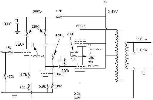
The first stage is kind of straight forward. The cathode voltage is supposed to be 2 volts (not the 20 that the Sams mistakenly says). Actual measurement is about 1.5. The input has what is known as a stopper resistor, which minimizes high frequency oscillation. The gain of the stage is about 7.8. If one looks at the cathode circuit closely, one can imagine it as also being a common grid amplifier, where the input is the cathode, and the cathode resistor is a stopper, whereas the 390 ohm resistor is the input impedance. This allows both the input signal and the fed back signal to mix in the tube. This brings the tube's gain down to about 6 (2200/390 || 1/Gm+4700).
The output of that triode goes through a 0.0012 µF capacitor. This cap has a roll off at about 200 Hertz. This is OK, because it will all be brought back to a flat level with what is below it by NFB (more later). It feeds the top 6BQ5, which has a gain of about 25 (tube hooked as pentode should be a max of 500). So overall theoretical gain is 7.8 times 25 or 195. Ah, but we really need to include the output transformer in this because it steps down the voltage. So assuming that the output tubes go full swing at a B+ of 320 volts, we get the RMS voltage, or 320 X 0.707 to get 226 volts. Now, assuming that the output is the 18 watts that the EICO called for with this transformer, then we use the formula to get voltage from power and resistance (assuming 16 ohms impedance is equivalent to impedance), or V=SQRT(PR), or V=SQRT(18X16) =16.9. So, the 226 volts gets cut down to 16.9 volts. Which means that that stage amplifies the signal, assuming with bias set at 12.7 volts (measured) (12.7*.707 for RMS, or 8.98 volts) then from 8.98 to 16.9 volts is about 1.88. So open loop gain is actually about 7.8 times 1.88, or 14.66. This amp needs a 1 volt signal to put out full power open loop.
The output of this triode also goes through a voltage divider/grid resistor (for both the top pentode and the phase inverter triode) to the phase inverter triode. This stage has a gain of about 6.4 (theoretically). Not exactly even gain with the first triode, but with NFB close enough. This then amplified but inverted signal gets passed through a 0.047 microfarad capacitor that has a roll off at 18 hertz with the 220K grid resistor at the pentode.
So, the resultant signal then passes through the transformer with all of its distortions and brought back to the input to both attenuate the amplifier overall to a gain of 6. So for full power this amp needs 16.9/6 or 2.8 volts for full power out. Not a problem. I have a preamplifier that will provide this.
Now notice that all four output tubes are tied together at the cathodes going through one resistor? Usually, only one pair per channel shares a common cathode resistor for push pull operation. Although each output tube could use individual resistors, this would require a negative bias supply to bring the tubes close to cut off (class AB1 is where the tubes are close to cut off so at low volume levels they act as class A bias. At louder volume levels it behaves as a class B amp. Class B operation has tubes at cut off, but at low volume levels sound is distorted). Tying them together allows for easier self biasing schemes and the transition of a signal from one tube to the other. This usually requires matched pairs of tubes in order for both tubes to be biased at the same level (matched pair is where both tubes flow the same current at the same voltage level). I was fortunate to get a matched quad. I say this because all four have a common current source. Also with a pair of tubes in push pull, if there is a difference between the phase inverter and the output of the first tube (which we have here), the differential nature of the output tubes causes there to be a balance of output, because both signals add within the differential pair, so the output of each tube is equal.
Anyway, I was confused about how the signal didn't mix between the two channels. But I figured that is was the same reason that a long tailed pair did not have a signal at that point. Common currents cancel at that point. The bypass capacitor takes care of anything that leaks past. On the other hand, I am of the opinion that it also aids in the stereo separation. Anything that does leak past to the other channel would be out of phase with the first channel, so it might create an imaging effect. On the other hand, it does seem to make for a stiffer current control for each tube. If one is going positive, two of the others remain idle at a fixed current (This condition would be for one channel getting a pure sine wave). This is also an interesting way to make the amp more efficient. One gets the maximum gain for that one tube's full positive swing, because for that moment it only sees the resistor as its own cathode resistor. So it can provide its maximum power level while idling at a low power level.
As far as the imaging effect, I say this because of the similarity of another amplifier made by Steve Deckert at Decware. His single ended amplifier can also be bridged for 10 watts power. But when used as an SE amp, the two output tubes share a single cathode resistor also. He and others claim to have a surrounding effect from the amp. I get the same kind of imaging from this amp. ]]""

Se ho preso una cantonata, ditemelo pure

Saluti
JJT
Avatar utente
dueeffe
senior member
Messaggi: 1659
Iscritto il: 12 set 2007, 16:13
Località: Italy

Messaggio da dueeffe »

-->OT

(che tanto l'ultimate non mi piace :D )

TO<--

** ... presero le ossa dei padri e con i grossi femori uccisero i figli così che questi non possano fare come loro ... **


Originally posted by gluca - 21/08/2008 : 01:02:16

OT


Stamattina ad Ancona ho visto una "valvolina" dentro una bacheca.
Ho chiesto se ne avevano delle altre, e me ne hanno date due.
Ritoccherò l'Ultimate usando tali "valvoline", così sarai contento.
; )


Immagine
(la foto come al solito non è delle migliori, visto che uso il mio "solito" N95)


C’è scritto: Eimac 8189 - 4PR1000A
:D


/OT


------------------------------

"You can get more with a kind word and a gun than you can with a kind word alone."
(Al Capone)
Μὴ δῶτε τὸ ἅγιον τοῖς κυσίν, μηδὲ βάλητε τοὺς μαργαρίτας ὑμῶν ἔμπροσθεν τῶν χοίρων, μήποτε καταπατήσουσιν αὐτοὺς ἐν τοῖς ποσὶν αὐτῶν καὶ στραφέντες ῥήξωσιν ὑμᾶς
Avatar utente
UnixMan
sostenitore
Messaggi: 12096
Iscritto il: 27 ott 2005, 22:34
Località: L'Aquila (Italy)
Has thanked: 79 times
Been thanked: 48 times

Messaggio da UnixMan »

Stamattina ad Ancona ho visto una "valvolina" dentro una bacheca.
Ho chiesto se ne avevano delle altre, e me ne hanno date due.
Ritoccherò l'Ultimate usando tali "valvoline", così sarai contento. ; )


Originally posted by dueeffe - 21/08/2008 :  15:06:44
quello si` che sarebbe un vero Xtreme! :p :p :D

Ciao,
Paolo.
Ciao, Paolo.

«Se tu hai una mela, e io ho una mela, e ce le scambiamo, tu ed io abbiamo sempre una mela per uno. Ma se tu hai un'idea, ed io ho un'idea, e ce le scambiamo, allora abbiamo entrambi due idee.»
same
starting member
Messaggi: 442
Iscritto il: 30 dic 2007, 00:17
Località: zena

Messaggio da same »

se uso un trafo da step down 230 to 120 di adeguato amperaggio, seguito da due diodi SS ed un CLC , posso lavorare le 6Y6 ? PSU designer mi dice che ho sui 186 V, ma, come quelli che non sanno usar bene il BASS PC, non sono sicuro di aver impostato bene i parametri ...


Originally posted by jorge toribio - 21/08/2008 :  01:50:15
sicuro?

186V mi sembrano tanti.... a meno che il trasformatore sia talmente sovradimensionato da lavorare praticamente a vuoto..

giorgio
giorgio
Avatar utente
JJT
average member
Messaggi: 959
Iscritto il: 25 dic 2007, 19:40
Località: Santa Fe - Argentina

Messaggio da JJT »

Sicuro un paio di Berlusconis, niente affatto, devo aver sbagliato a dimensionare qualcosa, se sapessi cosa sarei in camino..
Qui ci vuole tubes for dummies
Avatar utente
JJT
average member
Messaggi: 959
Iscritto il: 25 dic 2007, 19:40
Località: Santa Fe - Argentina

Messaggio da JJT »

Immagine

Immagine
same
starting member
Messaggi: 442
Iscritto il: 30 dic 2007, 00:17
Località: zena

Messaggio da same »

Immagine

Immagine


Originally posted by jorge toribio - 22/08/2008 :  01:40:18
ok, 161Vcc mi quadra :)

Occhio che mi sembra che il tuo trasformatore abbia soltanto un secondario a 120V, per usare quel tipo di raddrizzatore a doppia semionda devi avere due secondari (oppure uno di tensione doppia con presa centrale)
Con un solo secondario, se vuoi un raddrizzatore a doppia semionda, devi usare un ponte


giorgio
giorgio
Avatar utente
JJT
average member
Messaggi: 959
Iscritto il: 25 dic 2007, 19:40
Località: Santa Fe - Argentina

Messaggio da JJT »

Preziosissimo consiglio. Grazie mille.
JJT
Avatar utente
UnixMan
sostenitore
Messaggi: 12096
Iscritto il: 27 ott 2005, 22:34
Località: L'Aquila (Italy)
Has thanked: 79 times
Been thanked: 48 times

Messaggio da UnixMan »

Con un solo secondario, se vuoi un raddrizzatore a doppia semionda, devi usare un ponte


Originally posted by same - 22/08/2008 :  16:22:07
se vuoi usare i diodi a vuoto ma vuoi evitare di usarne quattro, puoi fare un ponte ibrido, due diodi SS e due diodi a vuoto... su quel programma pero` non c'e`. :D

Ciao,
Paolo.
Ciao, Paolo.

«Se tu hai una mela, e io ho una mela, e ce le scambiamo, tu ed io abbiamo sempre una mela per uno. Ma se tu hai un'idea, ed io ho un'idea, e ce le scambiamo, allora abbiamo entrambi due idee.»
Avatar utente
JJT
average member
Messaggi: 959
Iscritto il: 25 dic 2007, 19:40
Località: Santa Fe - Argentina

Messaggio da JJT »

Modello Chiapetta? L'avevo letto su di un vecchio CHF, e sembrato bella idea.
Pero questo secondo PP e uno sperimento degli esiti incerti, cosí. un ponte SS e la cosa piu pratica. I'altro, modello Plovati , usa una 5U4GB Sylvania e poi un CLC.
Rispondi
  • Argomenti simili
    Risposte
    Visite
    Ultimo messaggio